Dynamic modeling and analysis of diesel engine valve mechanism
-
摘要: 发动机配气机构有限元分析作为基础试验的重要支撑,在现代机械设计中非常必要. 以直列四缸柴油机配气机构性能优化设计为研究目标,系统计算与确定柴油机热力学与动力学关键参数. 首先采用多体动力学方法建立配气机构动力学模型,计算静应力有限元分析结果,得出零部件动力学模型中的模块参数. 然后利用Sharp 3D软件对配气机构进行动力学分析,基于分析参数进行配气机构凸轮轴强度分析优化. 最后通过有限单元分析功能,对主要的零部件进行力学分析. 结果表明:对配气机构动力学模型的分析结果可靠,有利于柴油机配气机构动力学设计和性能参数的改进与优化.Abstract: Finite element analysis of engine valve mechanism is very necessary in modern mechanical design as an important support for basic experiment. Aiming at the optimal design of the performance for in-line four-cylinder diesel valve mechanism, the key thermodynamic and dynamic parameters of diesel engine were calculated and determined systematically. Firstly, the dynamic model of valve mechanism was established by using multi-body dynamic method, the finite element analysis results of static stress were calculated, and the module parameters in the dynamics model of parts were obtained. Then, Sharp 3D software was used to analyze the dynamics of the valve mechanism, and the camshaft strength of the valve mechanism was analyzed and optimized based on the analysis parameters. Finally, the main parts of the mechanism were analyzed through the finite element analysis function. The results show that the analysis results of the dynamics model of the valve mechanism are reliable, which are beneficial to the improvement and optimization of the dynamics design and performance parameters for the diesel engine valve mechanism.
-
Key words:
- valve mechanism /
- valve group /
- cam /
- system dynamic modeling
-
表 1 柴油机设计基本参数
Table 1. Basic parameters of diesel engine design
名称 参数 冲程 四冲程 燃烧室 涡流室 气缸直径/mm 85 活塞行程/mm 100 气缸类型 直列四缸 压缩比 21 排量/L 2.27 最大功率/kW 39.7 最大功率时转速/(r·min−1) 3000 外形尺寸(长×宽×高)/(mm×mm×mm) 574×337.5×532 表 2 热力学计算拟定参数
Table 2. Proposed parameters of thermodynamic calculation
名称 参数 燃料低热值${{{{H}}} }_{\mu }$ 10140 过量系数α 1.3 残余废气系数γ 1.001 环境气压Ps/kPa 101 环境空气温度T0/K 296 空气预热升高温度∆T/K 5 压缩多变指数n1 1.31 定容燃烧最高爆发压力${ { {P} }_{\text{z} } }$/kPa 8000 热量利用系数ξ 0.85 膨胀多变指数n2 1.25 丰满系数φf 0.95 机械效率ηm 0.8 表 3 工作过程计算结果
Table 3. Calculation results of working process
名称 参数 1 kg柴油完全燃烧实际需要空气的物质的量M1/(mol·kg−1) 0.644 1 kg柴油完全燃烧后燃烧产物的物质的量M2/(mol·g−1) 0.675 实际分子变更系数$ \mathrm{\mu } $ 1.048 压缩始点气温Ta/K 101 压缩始点气压Pa/kPa 101 压缩终点气温Tc/K 775.8 压缩终点气压Pc/kPa 5450.403 压力升高比λ 1.47 定容燃烧终点温度Ty/K 1140.426 定压燃烧终点温度Tz/K 2156.35 初期膨胀比ρ 1.98 膨胀终点气温Tb/K 1194.898 膨胀终点气压Pb/kPa 417.972 表 4 发动机性能计算结果
Table 4. Calculation results of engine performance
名称 参数 气缸容积Vh/L 0.567 燃烧室容积Vc/L 0.028 理论平均指示压力P/kPa 1270.485 实际平均指示压力Pe/kPa 1206.961 平均有效压力Pme/kPa 965.569 有效功率Ne/kW 40.257 充量系数ηv 0.934 指示热效率ηe 0.48 有效燃油消耗率be/(g·(kw·h−1)) 162.954 进气流量Q/(kg·s−1) 0.691 表 5 配气正时参数表
Table 5. Parameters of valve timing
名称 参数 进气门间隙/mm 0.30~0.45 排气门间隙/mm 0.30~0.45 进气门提前角/(°) 52 排气门提前角/(°) 50 进气门迟闭角/(°) 50 排气门迟闭角/(°) 52 进气门最大升程/mm 10 排气门最大升程/mm 10 摇杆传动比 1.6 表 6 工作段拟定参数
Table 6. Proposed parameters of the working section
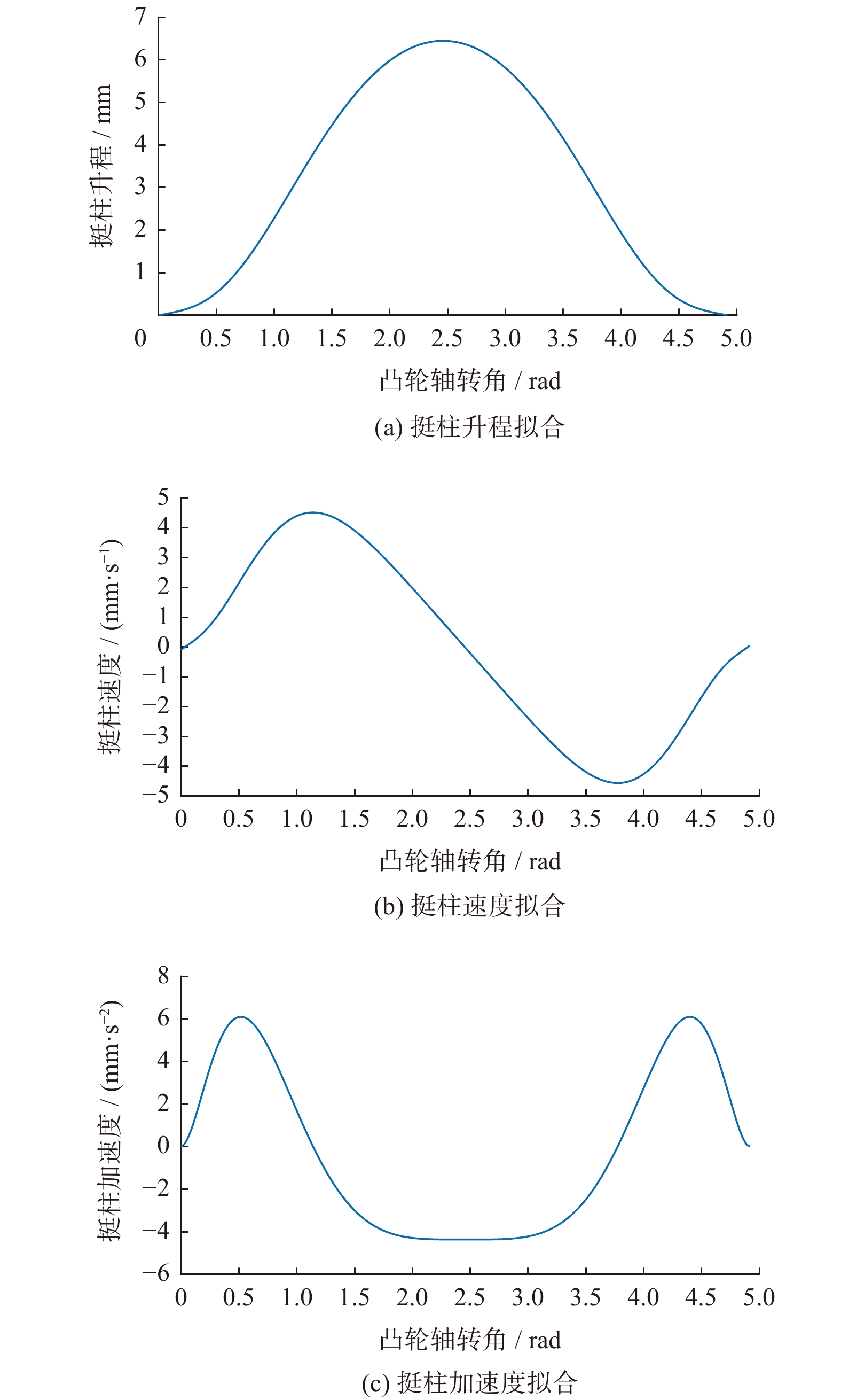
名称 参数 р 2 q 6 r 10 s 14 挺柱最大升程/mm 6.45 凸轮工作段转角/(°) 141 表 7 凸轮轴力学性能
Table 7. mechanical properties of camshaft
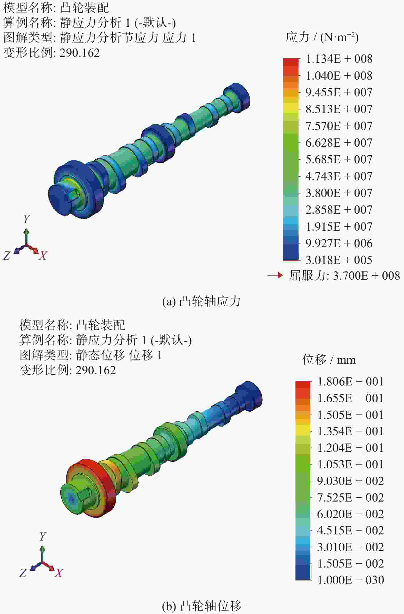
名称 参数 屈服强度/($ \mathrm{N}\cdot{\mathrm{m}}^{-2} $) $ 3.7{\times 10}^{8} $ 张力强度/($ \mathrm{N}\cdot{\mathrm{m}}^{-2} $) $ 6{\times 10}^{8} $ 弹性模量/($ \mathrm{N}\cdot{\mathrm{m}}^{-2} $) $ 1.9{\times 10}^{11} $ 泊松比 $ 2.7{\times 10}^{-1} $ 质量密度/($ \mathrm{k}\mathrm{g}\cdot{\mathrm{m}}^{-3} $) $ 7.3{\times 10}^{3} $ 抗剪模量/($ \mathrm{N}\cdot{\mathrm{m}}^{-2} $) $ 8.6{\times 10}^{10} $ 热扩张系数/K $ 1.2{\times 10}^{-5} $ -
[1] 赵海峰, 石坤鹏, 谢普康, 等. 配气机构自振频率计算方法研究[J] . 拖拉机与农用运输车,2020,47(1):39 − 43. [2] 杨宏斌, 李官运, 李静, 等. ZA型蜗杆副建模及动力学传动误差仿真分析[J] . 机械设计与制造,2021(9):125 − 128. doi: 10.3969/j.issn.1001-3997.2021.09.029 [3] 张学强. 柴油机配气机构动力学研究[D]. 石家庄: 石家庄铁道大学, 2014. [4] 陈睿, 张萍, 李育学. 某型柴油机配气机构动力学建模方法与性能仿真研究[J] . 襄阳职业技术学院学报,2015,14(5):33 − 37. [5] 牛文博. 发动机配气机构多体动力学建模与分析[D]. 天津: 天津大学, 2008. [6] 蔡卓洁. 汽油发动机进排气凸轮匹配对性能影响分析及试验研究[J] . 拖拉机与农用运输车,2019,46(3):23 − 28. [7] 商潭苏. 某柴油机配气机构数值模拟[J] . 拖拉机与农用运输车,2013,40(5):41 − 48. [8] 王晓磊, 王永钊, 刘祥. 新型集装箱板材上下料机械手动力学建模与仿真[J] . 机械设计与制造,2021(9):231 − 235. doi: 10.3969/j.issn.1001-3997.2021.09.052 [9] 李兴然. 配气机构多体系统动力学建模及仿真[D]. 太原: 中北大学, 2010. [10] 罗卫平, 陈曼华, 姜小菁, 等. 发动机配气机构系统的动力学建模及仿真分析[J] . 中国制造业信息化,2012,41(1):51 − 54. [11] 田甜, 李长玉, 胡泽澍, 等. 某卡车发动机的热力学-动力学建模及仿真分析[J] . 河南科学,2021,39(8):1217 − 1222. doi: 10.3969/j.issn.1004-3918.2021.08.003 [12] 刘涛, 张奇峰, 张运修, 等. 水下大臂展机械手动力学建模与仿真分析[J] . 液压与气动,2021,45(5):25 − 32. [13] 杨靖, 陶文祝, 何联格, 等. 气动发动机配气机构设计及优化研究[J] . 重庆理工大学学报(自然科学),2019,33(7):1 − 11. [14] 蒋玉宝, 段志辉, 吴仁哲. 汽车发动机中凸轮与挺柱接触应力的分析[J] . 装备机械,2019(1):9 − 13. [15] JAIN A, NUEESCH T, NAEGELE C, et al. Modeling and control of a hybrid electric vehicle with an electrically assisted turbocharger[J] . IEEE Transactions on Vehicular Technology,2016,65(6):4344 − 4358. doi: 10.1109/TVT.2016.2533585 [16] 张金伟. 汽车发动机配气机构设计思路分析[J] . 时代汽车,2019(10):77 − 78. doi: 10.3969/j.issn.1672-9668.2019.10.032 -


 下载:
下载:
