Study on ultimate bearing capacity of CHS X-joints strengthened with CFRP
-
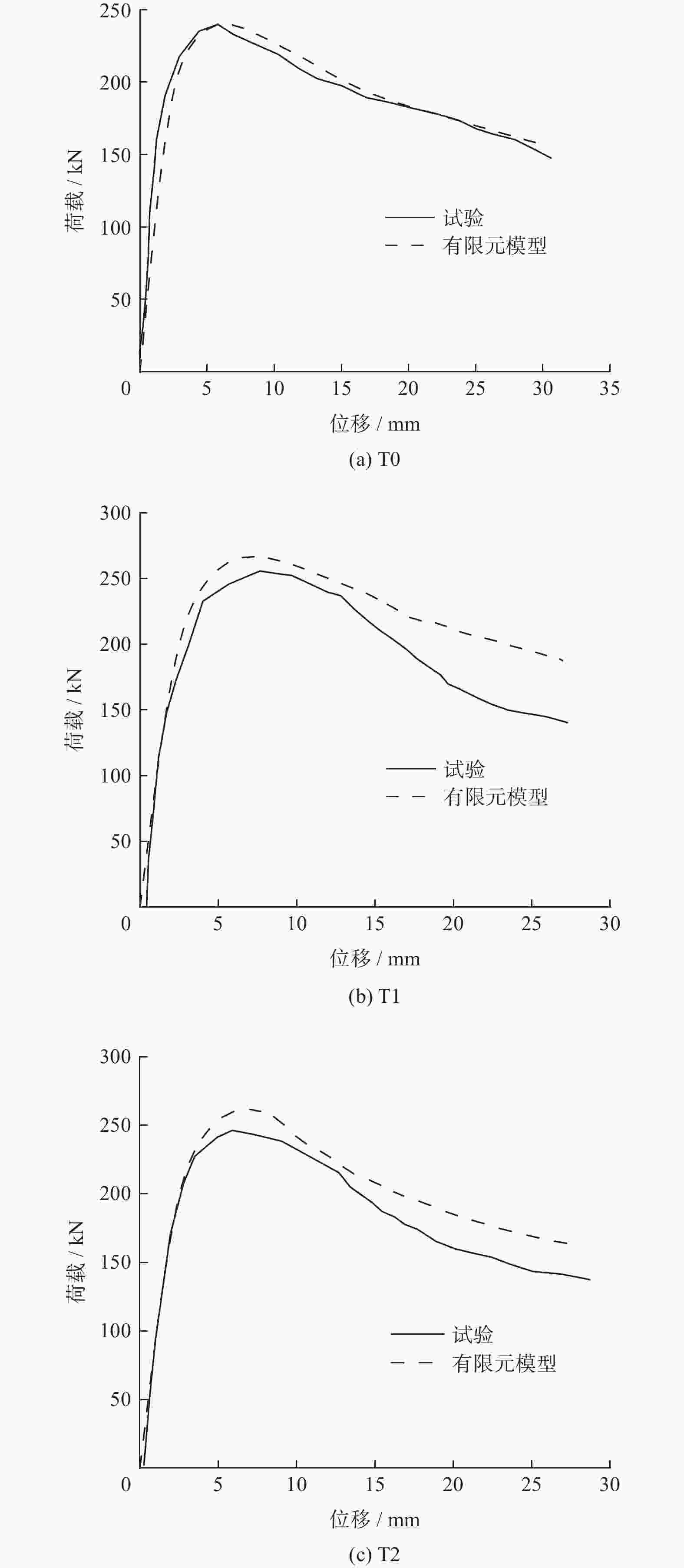
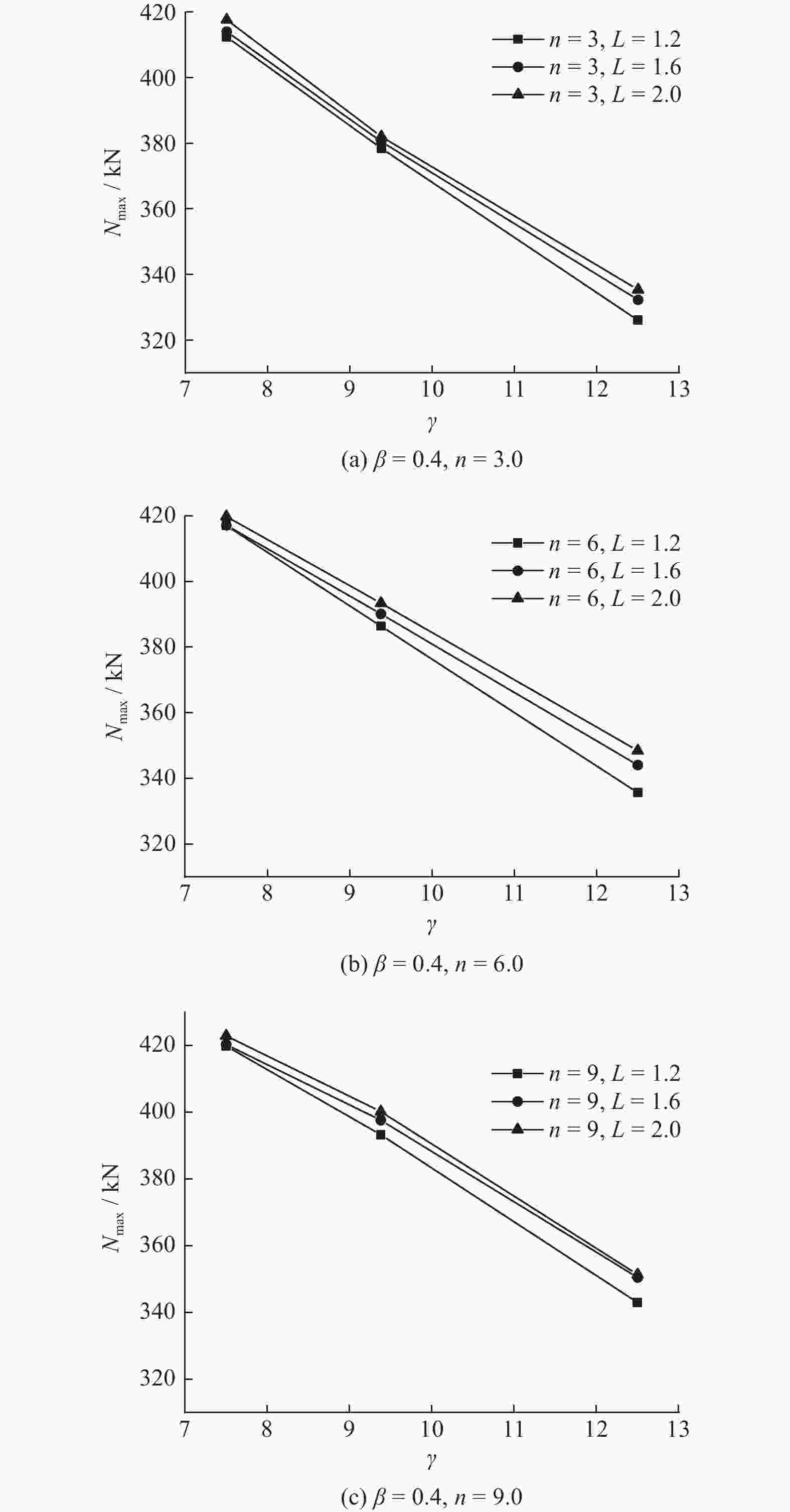
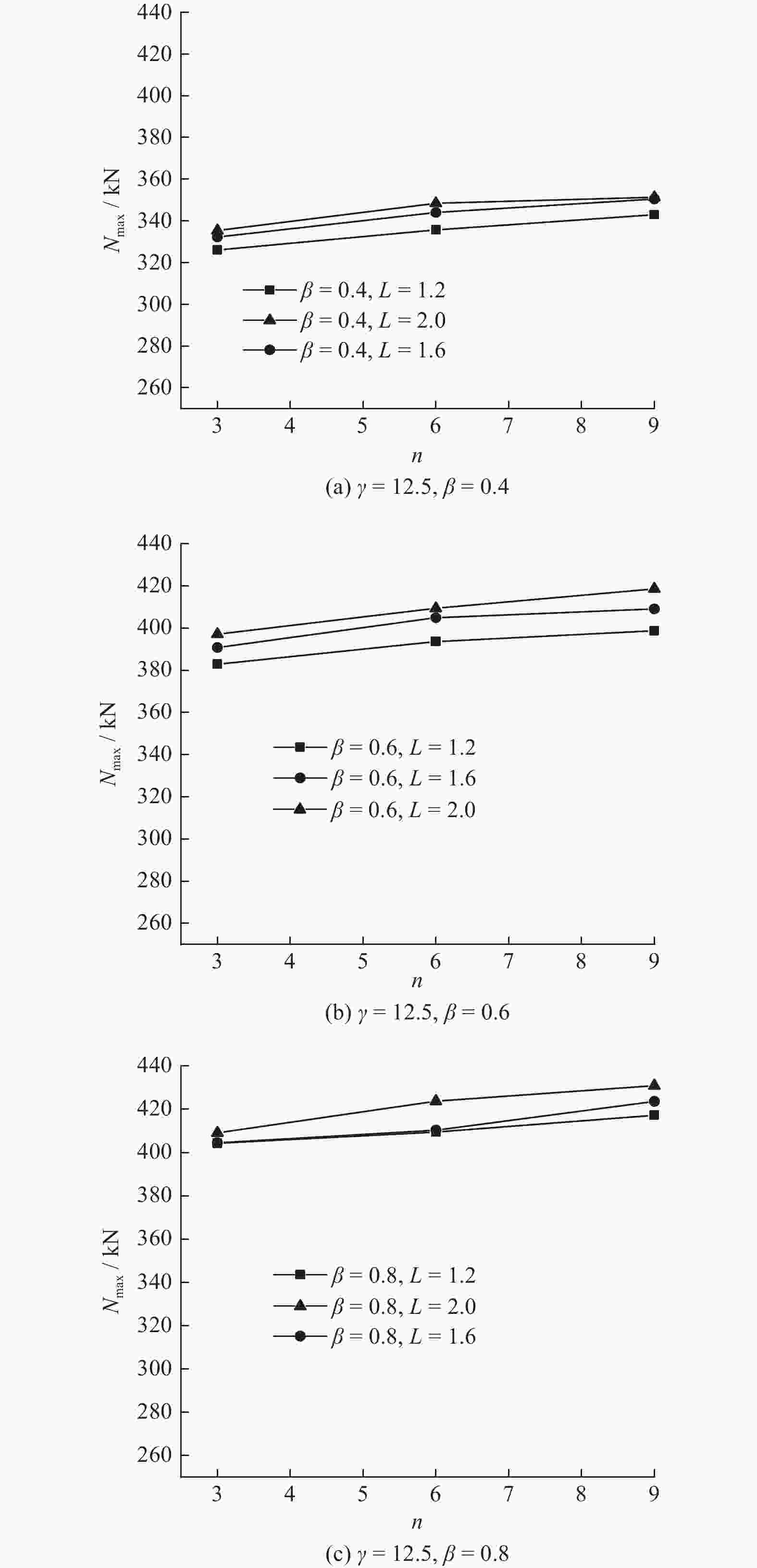
摘要: 为研究碳纤维增强塑料(CFRP)对X型圆钢管相贯节点的影响,对ABAQUS有限元软件进行二次开发,运用Fortran语言将VGM模型编译成VUSDFLD子程序对90个节点模型进行有限元分析,并研究支主管外径比β、主管径厚比γ、CFRP黏贴长度与主管直径之比L、CFRP黏贴层数n对节点承载力的影响. 结果表明:CFRP可以减小节点的应力集中,提高节点的承载力,节点开裂会发生在相贯线鞍点焊缝内侧与支管相交的焊根处,随着荷载增加,裂纹会从焊缝鞍点沿着相贯线向冠点发展. 对节点进行参数分析可以发现:随着γ的增加,节点极限承载力逐渐减小;随着β的增大,节点极限承载力逐渐增加;随着n和L的增加,节点极限承载力会有所提高. 本文节点的破坏发生在焊缝,提出CFRP加固X型圆钢管相贯节点焊缝承载力建议公式,对比有限元结果可以发现,节点主管壁厚较小,支管外径较大时,拟合公式的结果存在不安全.Abstract: In order to study the influence of carbon fiber reinforced plastic (CFRP) on the X-shaped circular steel tubular joints, the ABAQUS finite element software was redeveloped. The VGM model was compiled into the VUSDFLD subroutine by Fortran language. The finite element analysis of 90 joint models was carried out, and the effects of the ratio of the outer diameter of the branch to the main pipe β, the ratio of the diameter to the thickness of the main pipe γ, the ratio of the length of CFRP to the diameter of the main pipe L, and the number of CFRP layers n on the bearing capacity of the joints were studied. The results show that CFRP can reduce the stress concentration of the joint and improve the bearing capacity of the joint. The cracking of the joint will occur at the weld root where the inner side of the saddle point weld of the intersecting line intersects with the branch pipe. With increasing of the load, the crack develops from the weld saddle point along the intersecting line to the crown point. Parameters analysis of the joint show that with the increasing of γ, the ultimate bearing capacity of the joint decreases gradually, with the increasing of β, the ultimate bearing capacity of the joint increases gradually, with the increasing of n and L, the ultimate bearing capacity of the joint will increase. For the failure of the joint occured in the weld, the formula for the weld bearing capacity of the CFRP strengthened X-shaped circular steel tube intersecting joint was proposed. Compared with the finite element results, it can be found that the results of the formula fitted are unsafe when the wall thickness of the main pipe of the joint is small and the outer diameter of the branch pipe is large.
-
表 1 节点试件几何尺寸
Table 1. Geometric dimensions of joint specimens
节点类型 主管尺寸/
mm支管尺寸/
mmCFRP
层数CFRP长度/
mmCFRP铺设
方向T0 Φ194 × 6 Φ127 × 6 — — — T1 Φ194 × 6 Φ127 × 6 2 682 [0°/90°] T2 Φ194 × 6 Φ127 × 6 2 682 [45°/135°] 表 2 断裂参数
Table 2. Fracture parameters
材料 η 特征长度L* 下限 平均值 上限 母材 2.55 0.087 0.201 0.473 熔敷金属 2.63 0.062 0.202 0.311 热影响区 2.53 0.072 0.329 0.671 表 3 CFRP材料参数
Table 3. CFRP material parameters
MPa 纵向弹性
模量横向弹性
模量泊松比 纵向剪切
模量横向剪切
模量230000 40000 0.27 24000 14300 表 4 Hashin失效准则参数
Table 4. Hashin failure criterion parameters
MPa 纵向拉伸
强度纵向压缩
强度横向拉伸
强度横向压缩
强度纵向剪切
强度横向剪切
强度1830 895 31.3 124.5 72.0 62.3 表 5 管节点几何尺寸
Table 5. Geometric dimensions of tubular joints
mm 主管尺寸 支管尺寸 焊脚尺寸hf 焊缝计算长度lw θ/(°) Φ150 × 6 Φ60 × 6 7.2 187.43 90 Φ150 × 6 Φ90 × 6 7.2 282.98 90 Φ150 × 6 Φ120 × 6 7.2 390.87 90 Φ150 × 8 Φ60 × 6 7.2 187.43 90 Φ150 × 8 Φ90 × 6 7.2 282.98 90 Φ150 × 8 Φ120 × 6 7.2 390.87 90 Φ150 × 10 Φ60 × 6 7.2 187.43 90 Φ150 × 10 Φ90 × 6 7.2 282.98 90 Φ150 × 10 Φ120 × 6 7.2 390.87 90 表 6 参数取值
Table 6. Parameter values
参数 取值 β 0.4、0.6、0.8 γ 7.50、9.38、12.50 L 1.2、1.6、2.0 n 3、6、9 CFRP厚度/mm 0.167 CFRP黏贴方式 CFRP碳纤维束与主管轴线平行成0°方向 表 7 X型圆钢管节点承载力结果
Table 7. Bearing capacity results of X-type circular steel tubular joints
编号 γ β n L NK/kN Nmax/kN ψ X1 7.5 0.4 0 0 370.11 399.74 0 X2 7.5 0.4 3 1.2 380.56 412.34 1.032 X3 7.5 0.4 3 1.6 380.72 413.98 1.036 X4 7.5 0.4 3 2.0 386.35 417.60 1.045 X31 9.38 0.4 0 0 344.70 362.22 0 X32 9.38 0.4 3 1.2 359.63 378.43 1.045 X33 9.38 0.4 3 1.6 361.61 380.47 1.050 X34 9.38 0.4 3 2.0 363.13 381.98 1.055 X61 12.5 0.4 0 0 287.86 311.51 0 X62 12.5 0.4 3 1.2 308.15 326.04 1.047 X63 12.5 0.4 3 1.6 311.66 332.28 1.067 X64 12.5 0.4 3 2.0 314.40 335.38 1.077 X65 12.5 0.4 6 1.2 314.99 335.68 1.078 X66 12.5 0.4 6 1.6 322.13 344.05 1.104 X67 12.5 0.4 6 2.0 325.94 348.45 1.119 X68 12.5 0.4 9 1.2 321.32 342.96 1.101 X69 12.5 0.4 9 1.6 327.72 350.48 1.125 X70 12.5 0.4 9 2.0 337.45 351.36 1.128 X71 12.5 0.6 0 0 357.14 367.14 0 X72 12.5 0.6 3 1.2 374.61 382.92 1.043 X73 12.5 0.6 3 1.6 381.75 390.81 1.064 X74 12.5 0.6 3 2.0 387.93 397.17 1.082 X75 12.5 0.6 6 1.2 383.71 393.61 1.072 X76 12.5 0.6 6 1.6 388.80 404.93 1.103 X77 12.5 0.6 6 2.0 397.22 409.40 1.115 X78 12.5 0.6 9 1.2 390.35 398.75 1.086 X79 12.5 0.6 9 1.6 397.97 409.09 1.114 X80 12.5 0.6 9 2.0 408.27 418.64 1.140 X81 12.5 0.8 0 0 374.03 385.16 0 X82 12.5 0.8 3 1.2 395.20 404.31 1.050 X83 12.5 0.8 3 1.6 399.78 404.52 1.050 X84 12.5 0.8 3 2.0 404.11 409.09 1.062 X85 12.5 0.8 6 1.2 398.74 409.46 1.063 X86 12.5 0.8 6 1.6 406.93 410.32 1.065 X87 12.5 0.8 6 2.0 415.39 423.74 1.100 X88 12.5 0.8 9 1.2 408.64 417.28 1.083 X89 12.5 0.8 9 1.6 417.73 423.66 1.100 X90 12.5 0.8 9 2.0 425.57 430.92 1.119 注:Nk为节点开裂时的荷载值;Nmax为节点极限荷载值;ψ为极限承载力提高系数. 表 8 有限元模拟与公式计算结果对比表
Table 8. Comparison between finite element simulation and formula calculation results
节点
编号有限元
模拟ψ公式
计算ψp有限元模拟节点极
限承载力Nmax/kN公式计算焊缝承载
力设计值N/kNX82 1.050 1.046 404.31 414.99 X83 1.050 1.056 404.52 418.97 X84 1.062 1.065 409.09 422.58 X85 1.063 1.069 409.46 424.30 X86 1.065 1.084 410.32 430.08 X87 1.100 1.097 423.74 435.32 X88 1.083 1.088 417.28 431.59 X89 1.100 1.106 423.66 438.79 X90 1.119 1.122 430.92 445.31 -
[1] 黄政华, 张其林, 杨宗林, 等. 平面钢管桁架的面外稳定分析模型研究[J] . 土木工程学报,2011,44(5):49 − 56. [2] 陈以一, 陈扬骥. 钢管结构相贯节点的研究现状[J] . 建筑结构,2002,32(7):52 − 55. [3] 丁芸孙. 圆管结构相贯节点几个设计问题的探讨[J] . 空间结构,2002,18(4):13 − 15. [4] 蔡艳青, 邵永波, 岳永生. 环口板加强型T型圆钢管节点承载力的试验研究[J] . 工程力学,2011,28(9):90 − 94, 102. [5] HAN J, LIANG Y. The strength research of pressure pipeline reinforced with CFRP[J] . Applied Mechanice and Materials,2013,4:446 − 447. [6] ELCHALAKANI M. Rehabilitation of corroded steel CHS under combined bending and bearing using CFRP[J] . Journal of Constructional Steel Research,2016,125:26 − 42. [7] 王东锋, 邵永波, 欧佳灵. CFRP加固含腐蚀缺陷圆钢管混凝土短柱轴压承载力试验研究[J] . 工程力学,2021,38(10):188 − 199. [8] KABIR, M. Z. A. NAZARI. Enhancing ultimate compressive strength of notch embedded steel cylinders using overwrap CFRP patch[J] . Applied Composite Materials,2011,19(3/4):723 − 738. [9] 宋生志, 魏建军, 陈成. 碳纤维布(CFRP)加固T形圆钢管节点的静力性能研究[J] . 建筑钢结构进展,2015,17(2):57 − 64. [10] FU Y G, TONG L W, HE L, et, al. Experimental and numerical investigation on behavior of CFRP-strengthened circular hollow section gap K-joints[J] . Thin-Walled Structures,2016,102:80 − 97. doi: 10.1016/j.tws.2016.01.020 [11] 李康帅, 邵永波. CFRP加固TT型空心截面管节点轴压性能试验[J] . 空间结构,2022,28(3):86 − 91 , 76. [12] 王伟, 廖芳芳, 陈以一, 等. 基于微观机制的钢结构节点延性断裂预测与裂后路径分析[J] . 工程力学,2014,31(3):101 − 108, 115. [13] RICE J R, TRACEY D M. On the ductile enlargement of voids in triaxial stress fields[J] . Journal of the Mechanics and Physics of Solids,1969,17(3):201 − 217. [14] LIAO F F, WANG W, CHEN Y Y, et al. Parameter calibrations and application of micromechanical fracture models of structural steels[J] . Structural Engineering & Mechanics,2012,42(2):153 − 17. [15] 尹越, 车鑫宇, 韩庆华, 等. 基于微观断裂机制的XK型相贯节点极限承载力分析[J] . 土木工程学报,2017,50(7):20 − 26, 121. [16] 马栋. 碳纤维加固圆钢管T型相贯节点受压性能试验研究[D]. 青岛: 山东科技大学, 2016. [17] 邵永波, 史曼瑜. CFRP加固含凹痕缺陷的T形管节点静力性能研究[J] . 建筑钢结构进展,2020,22(4):68 − 74. [18] 住房和城乡建设部. 钢结构设计标准: GB 50017—2017 [S]. 北京: 中国建筑工业出版社, 2018. -


 下载:
下载:


