

Study on influence of anodic channel groove structure on performance of PEM electrolyzer
-
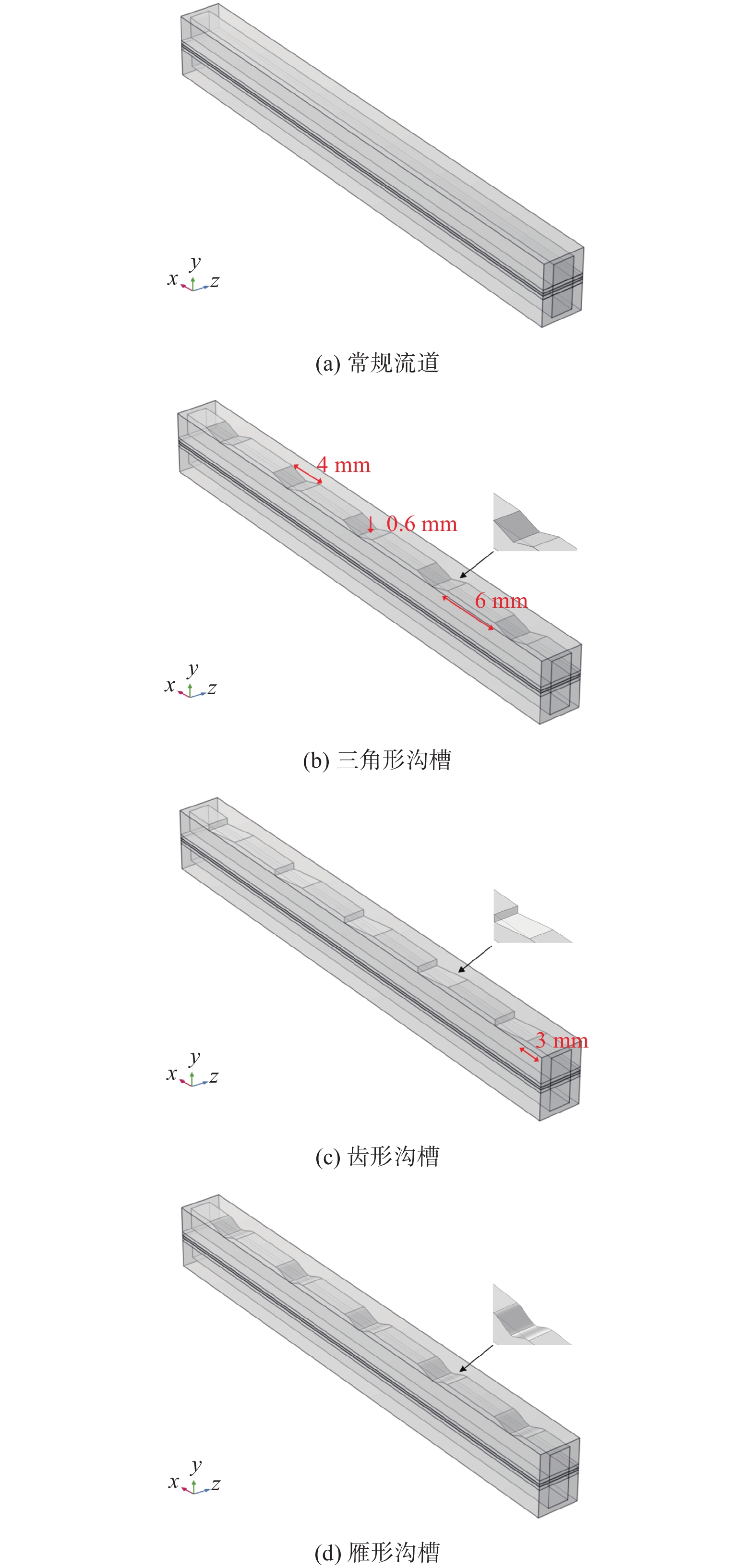
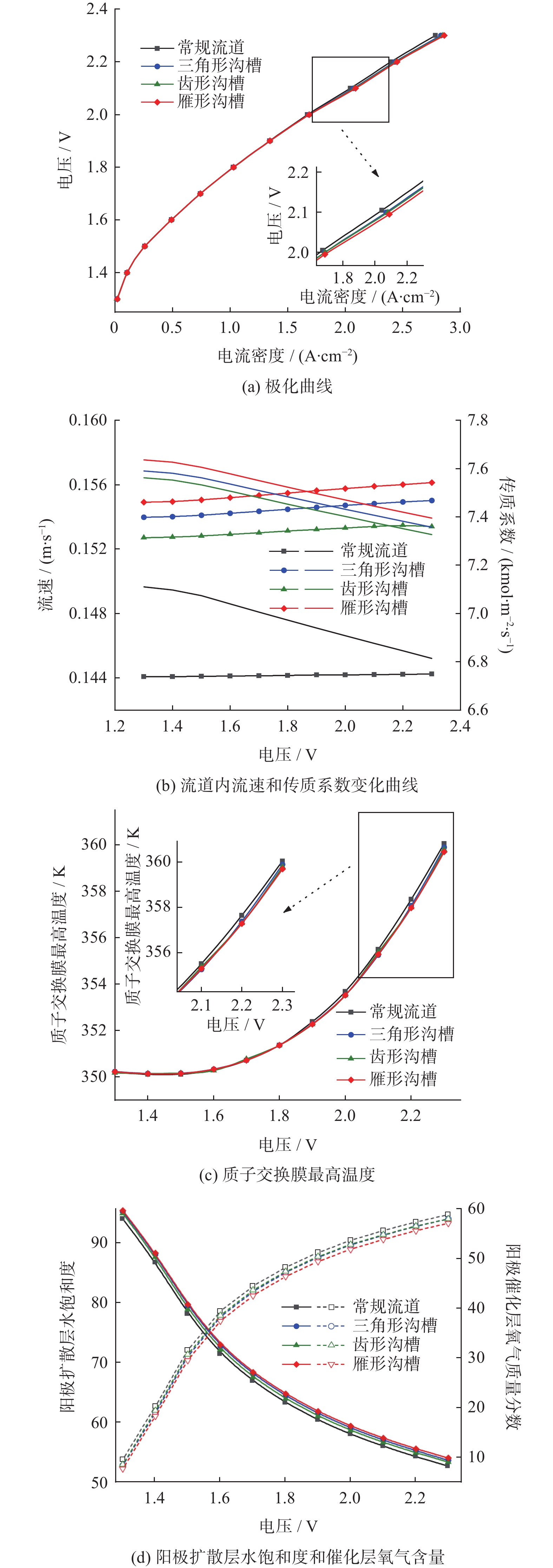
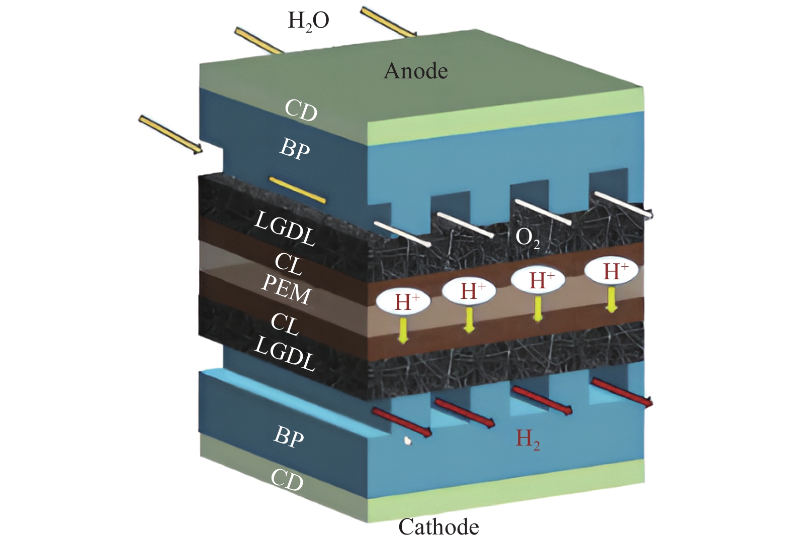
摘要: 建立质子交换膜(proton exchange membrane, PEM)单电解槽传热传质两相流稳态模型,研究阳极流道中不同沟槽结构(三角形、齿形和雁形)对PEM电解槽性能的影响,探究沟槽深度、数量及间距等参数的影响。结果表明,在阳极流道中引入沟槽可改善电化学性能,增强传热传质,提高电解槽效率,且雁形沟槽优化效果最佳。在0.4 ~1.6 mm深度范围,0.8 mm对应的电解槽性能最佳。相较于常规流道结构,优化后电解槽达到相同电流密度所需的电势更低,阳极区域内水饱和度(体积分数)和氧气含量(体积分数)更佳,质子交换膜温度更低,电解槽性能得到提升。Abstract: A steady-state two-phase heat and mass transfer model was developed for a single proton exchange membrane (PEM) electrolyzer to investigate the effects of different groove structures (triangular, tooth-shaped and goose-shaped) on its performance. The influence of groove depth, number and spacing was examined. The results show that incorporating grooves in the anode flow channel can improve electrochemical performance, enhance the heat and mass transfer, and increase the efficiency of the electrolyzer, with the best optimization effect of the goose-shaped groove. Within the range of 0.4~1.6 mm in depth, the electrolyzer corresponding to 0.8 mm has the best performance. Compared to a conventional flow channel, the optimized electrolyzer has a lower potential to achieve the same current density, has a better proportion of water saturation and oxygen content in the anode region, and has a lower proton exchange membrane temperature, thereby improving the performance of the electrolyzer.
-
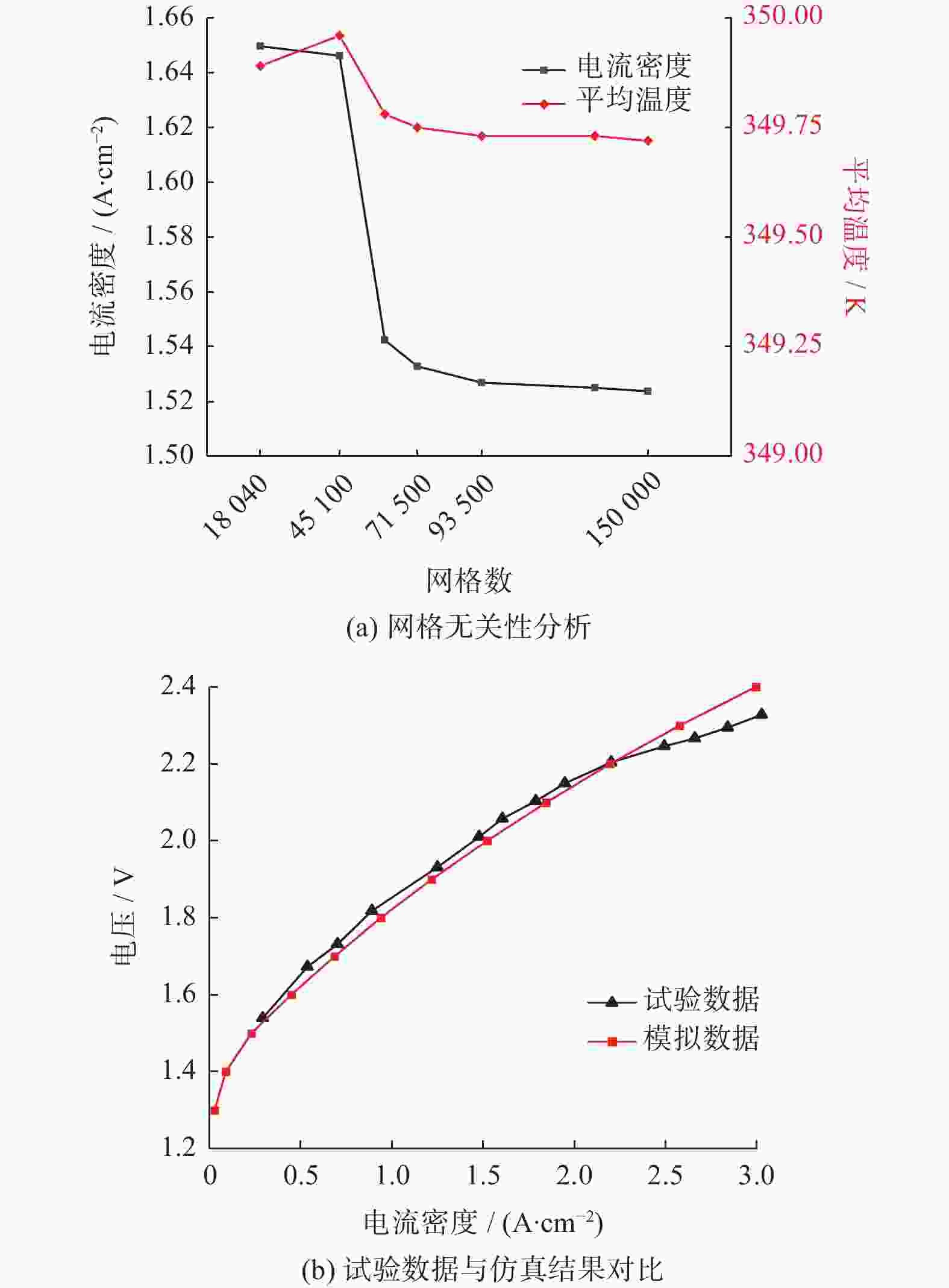
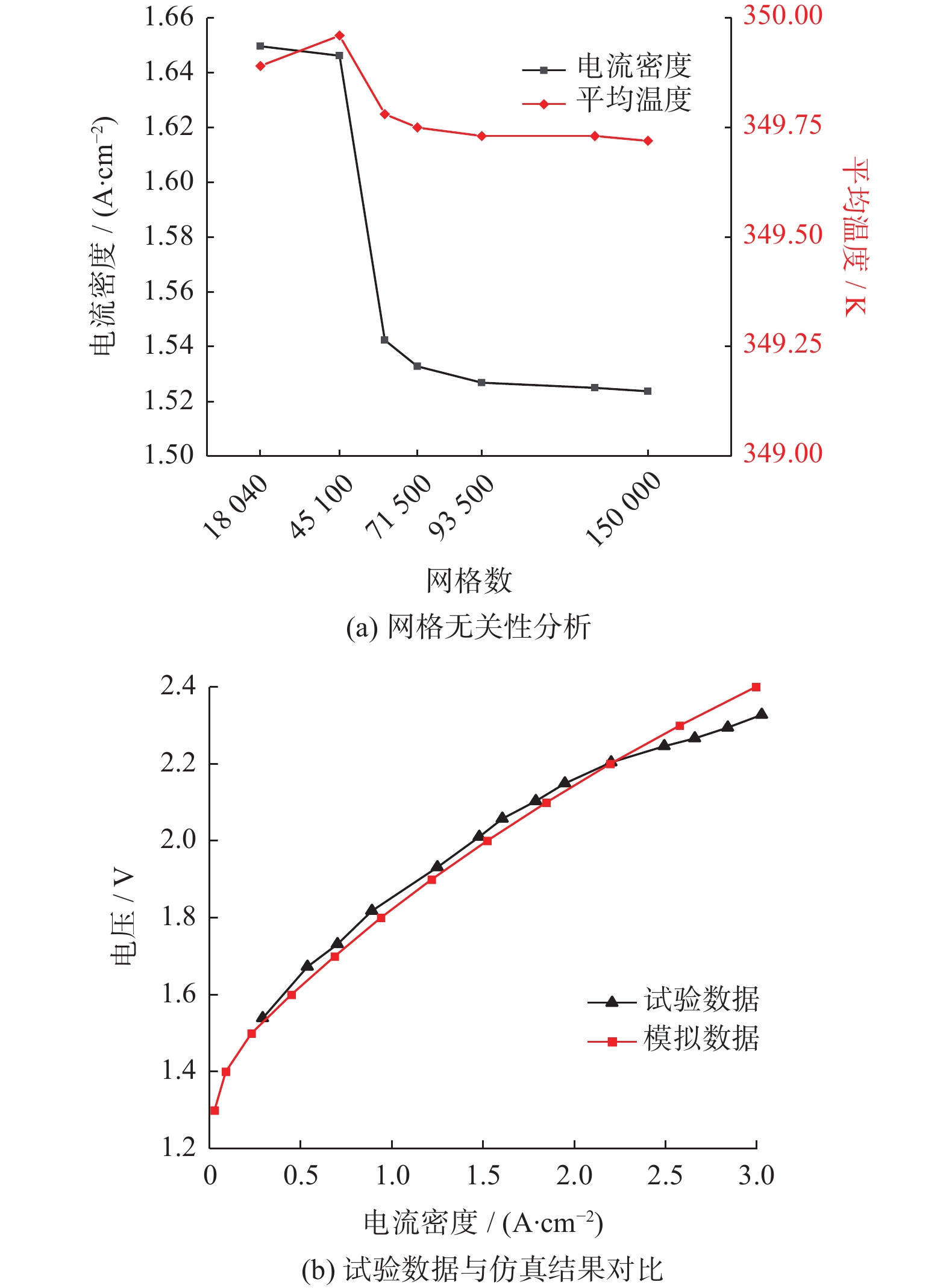
图 3 网格无关性分析和仿真结果与试验对比
Figure 3. Grid independence analysis and comparison of simulation results and experimental data
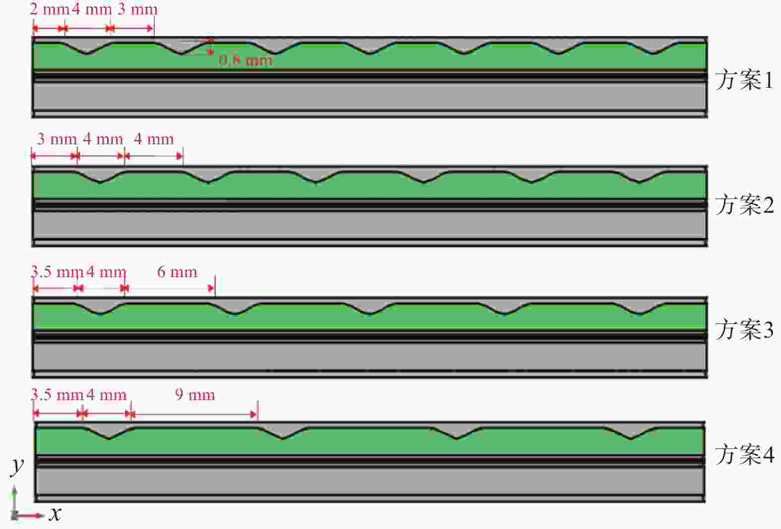
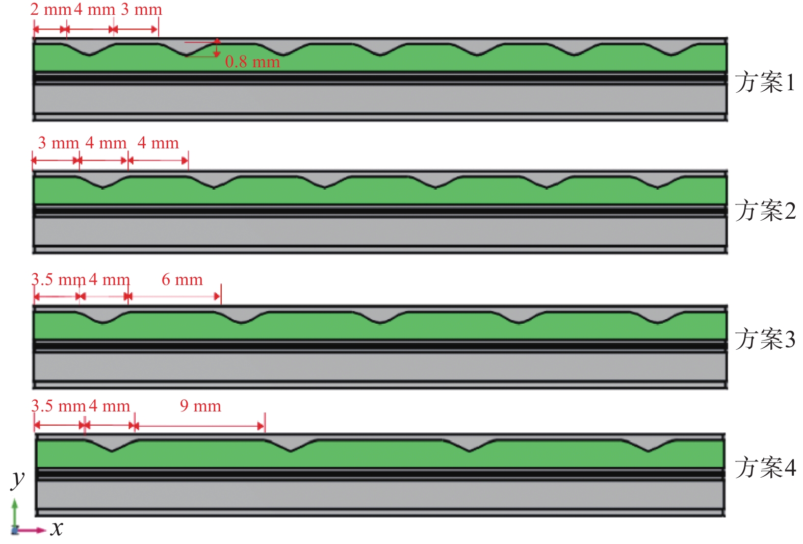
图 6 不同沟槽设计方案 x-y方向截面图
Figure 6. Cross sections of different trench design schemes along x-y direction
表 2 PEM模型几何结构参数
Table 2. Geometric structure parameters of PEM model
几何结构 数值/mm 电解槽长度 50 电解槽宽度 4 流道宽度 2 流道高度 2 双极板高度 2.5 催化层厚度 0.05 扩散层厚度 0.3 质子交换膜厚度 0.178  下载: 导出CSV
表 3 沟槽深度对PEM电解槽性能的影响
Table 3. Effect of groove depth on performance of PEM electrolyzer
沟槽深度/
mm电势/V 阳极扩散
层水饱和
度/%阳极扩散
层氧气含
量/%质子交换
膜最高温
度/K阳极流道
平均速度/
(m·s−1)0.4 2.0919 57.13 54.22 354.97 0.1508 0.6 2.0908 57.35 53.99 354.94 0.1559 0.8 2.0895 57.49 53.86 354.89 0.1600 1.0 2.0911 57.50 54.10 354.87 0.1623 1.2 2.0917 54.74 56.74 354.93 0.1381 1.4 2.0910 54.03 57.50 355.00 0.1357 1.6 2.0921 53.78 57.79 355.04 0.1403
下载: 导出CSV
表 4 沟槽布置方案
Table 4. Groove layout programme
沟槽布置
方案沟槽深度/
mm沟槽宽度/
mm沟槽距入口
宽度/mm沟槽间距/
mm沟槽
数量方案1 0.8 2 2 3 7 方案2 0.8 2 3 4 6 方案3 0.8 2 3.5 6 5 方案4 0.8 2 3.5 9 4
下载: 导出CSV
表 5 沟槽间距和数量对PEM电解槽性能的影响
Table 5. Effect of groove spacing and number on performance of PEM electrolyzer
沟槽布置方案 电势/V 阳极扩散层水饱和度/% 阳极扩散层氧气含量/% 质子交换膜最高温度/K 阳极流道
平均速度
/(m·s−1)方案1 2.0910 56.27 55.09 354.89 0.1636 方案2 2.0891 56.47 54.89 354.92 0.1589 方案3 2.0854 58.41 55.07 353.44 0.1547 方案4 2.0873 56.28 52.97 354.95 0.1507
下载: 导出CSV
-
[1] GARCIA-NAVARRO J C, SCHULZE M, FRIEDRICH K A. Detecting and modeling oxygen bubble evolution and detachment in proton exchange membrane water electrolyzers[J] . International Journal of Hydrogen Energy, 2019, 44(50): 27190 − 27203. doi: 10.1016/j.ijhydene.2019.08.253 [2] LI Y F, KANG Z Y, MO J K, et al. In-situ investigation of bubble dynamics and two-phase flow in proton exchange membrane electrolyzer cells[J] . International Journal of Hydrogen Energy, 2018, 43(24): 11223 − 11233. doi: 10.1016/j.ijhydene.2018.05.006 [3] CHANDESRIS M, MÉDEAU V, GUILLET N, et al. Membrane degradation in PEM water electrolyzer: numerical modeling and experimental evidence of the influence of temperature and current density[J] . International Journal of Hydrogen Energy, 2015, 40(3): 1353 − 1366. doi: 10.1016/j.ijhydene.2014.11.111 [4] MAJASAN J O, CHO J I S, MAIER M, et al. Effect of anode flow channel depth on the performance of polymer electrolyte membrane water electrolyser[J] . ECS Transactions, 2018, 85(13): 1593 − 1603. doi: 10.1149/08513.1593ecst [5] 张永恒, 李荣荣, 林志敏, 等. 小尺度沟槽表面和近距离布置光面构成通道中传热特性数值研究[J] . 工程热物理学报, 2016, 37(2): 378 − 384. [6] 邢晓慧. 质子交换膜电解池传热传质及流场结构研究[D] . 北京: 北京交通大学, 2020. [7] 谢峰, 王秀英, 雷小宝. 鲨鱼皮减阻结构的几何建模与数值分析[J] . 系统仿真学报, 2014, 26(7): 1472 − 1476. [8] WANG Z M, XU C, WANG X Y, et al. Numerical investigation of water and temperature distributions in a proton exchange membrane electrolysis cell[J] . Science China Technological Sciences, 2021, 64(7): 1555 − 1566. doi: 10.1007/s11431-021-1810-9 [9] WU L Z, ZHANG G B, XIE B, et al. Integration of the detailed channel two-phase flow into three-dimensional multi-phase simulation of proton exchange membrane electrolyzer cell[J] . International Journal of Green Energy, 2021, 18(6): 541 − 555. doi: 10.1080/15435075.2020.1854270 [10] SONG J, GUO H, YE F, et al. Mass transfer and cell performance of a unitized regenerative fuel cell with nonuniform depth channel in oxygen‐side flow field[J] . International Journal of Energy Research, 2019, 43(7): 2940 − 2962. doi: 10.1002/er.4472 [11] ZHOU H R, MENG K, CHEN W S, et al. 3D two‐phase and non‐isothermal modeling for PEM water electrolyzer: heat and mass transfer characteristic investigation[J] . International Journal of Energy Research, 2022, 46(12): 17126 − 17143. doi: 10.1002/er.8375 [12] MENG H. A two-phase non-isothermal mixed-domain PEM fuel cell model and its application to two-dimensional simulations[J] . Journal of Power Sources, 2007, 168(1): 218 − 228. doi: 10.1016/j.jpowsour.2007.03.012 [13] GUO H, GUO Q, YE F, et al. Three-dimensional two-phase simulation of a unitized regenerative fuel cell during mode switching from electrolytic cell to fuel cell[J] . Energy Conversion and Management, 2019, 195: 989 − 1003. doi: 10.1016/j.enconman.2019.05.069 [14] AUBRAS F, DESEURE J, KADJO J J A, et al. Two-dimensional model of low-pressure PEM electrolyser: two-phase flow regime, electrochemical modelling and experimental validation[J] . International Journal of Hydrogen Energy, 2017, 42(42): 26203 − 26216. doi: 10.1016/j.ijhydene.2017.08.211 [15] CAI Y H, FANG Z, CHEN B, et al. Numerical study on a novel 3D cathode flow field and evaluation criteria for the PEM fuel cell design[J] . Energy, 2018, 161: 28 − 37. doi: 10.1016/j.energy.2018.07.127 -

 下载:
下载:

 点击查看大图
计量
- 文章访问数: 532
- HTML全文浏览量: 338
- PDF下载量: 35
- 被引次数: 0
